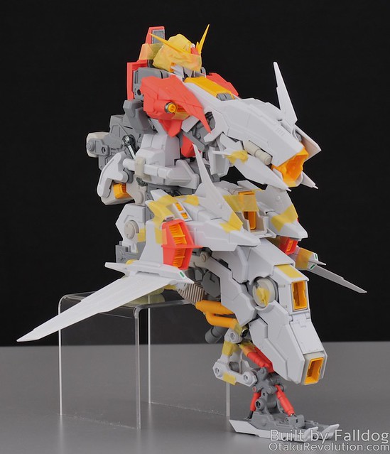
Welcome back to my multi-part review of the of Mechanicore’s 1/100 scale Tief Stürmer. In this section I'm going to review the head and primary torso components, sections 1 through 5.
Review Menu:
- Part 1: Kit Introduction
- Part 2: Head and Torso (Steps 1 through 5)
- Part 3: Booster Pods and Rear Booster Module (Steps 6 and 7)
- Part 4: Main Gun and Radar (Steps 8 and 9)
- Part 5: Arms, I-Field Generator, and Secondary Gun (Steps 10, 11, 12, and 17)
- Part 6: Rear Boosters and Booster Legs (Steps 13 through 16)
- Part 7: Stand and Final Assembly (Step 18 and 19)
- Part 8: Final Kit Review
Common Issues
This is a quick list of the common issues on the build. They apply pretty much across the board and pop up so much that I'd probably go crazy trying to specifically mention each time it occurs throughout the build.
- Beware pegs and holes with fitment issues. Whenever inserting pegs watch to make sure that the peg actually fit. Quite often they're too large for the hole they're supposed to go into. This can be resolved by a properly sized drill bit (use an hand held driver instead of an electric one, or be very careful, to avoid going through the other side of the piece) or with a fine round metal file to widen it from the inside out.
- Beware pieces who's sprue connection often coexists with an important piece. In other words, runners have been connected to the pieces themselves in areas that are also happen to be connection points to other parts of the kit. Never cut flush with the plastic to get it off the runner (which you shouldn't be doing anyway. For the second cut, make sure you check out the part and how it's going used to make sure you don't lop off something important.
- Beware pieces with subtle flashing around the connection points. Connection points may have subtle flashing issues that result in a poor fit. If something doesn't quite work like it should, make sure this is not the case before proceeding. Use of a hobby knife is recommended to clean these areas up.
Build Notes
- There are quite a few piece that really should be glued into place. Since I intend to go back and paint I'm holding things together with masking tape.
- Because I'm going back and repainting I'm not applying any of the metal detail parts at this point. When I finish the build, and add them, I'll add any additional thoughts regarding their application to this review.
The Head (Steps 1.1 - 1.3)
The head is the first part of the Tief Stürmer you build and it will quickly make you hate everything about the project.
Simply put, nothing on the head fits remotely well. Nearly everything is wonky in one way or another.
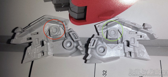
In step 1.1, the inner frame pieces don't tightly sit together, nor is there any connection point between the two pieces of green plastic used for the eyes. Note that the LED piece, LS2-A, comes preattached to the wiring it's associated with in the plastic tray. You may have to unwrap the bundles to identify which is the right one. When you go to throw on the outer armor in step 1.2 things go down hill further. For starters, there's an issue with the mold on one side where the connection point is deformed.
Note the red circled area on the left.
On top of that the armor seems to suffer from the issue where, when the top is squeezed together the bottom spreads about, and visa versa. The whole thing is going to need to be glued into place. In addition I'm not sure that the top piece sits really well so I'm worried that there will be an unsightly gap there even after things are clamped and glued.
In step 1.3 you add a lot of little pieces to the kit. Be aware that these can fit loosely and should be glued into place or else you might lose them forever.
The v-fin on my kit doesn't seem to fit in place well right now, probably just because the rest of the head where it connects to is still a mess. Be careful when removing the v-fin from the runner as there's no real distinction between the piece and nubs/runner at the bottom.
The Torso (Steps 2.1 through 5.11)
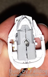
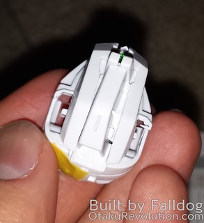
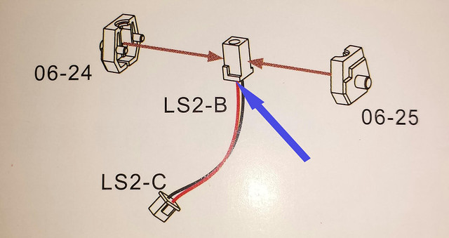
The first work with the LED wiring comes into play in step 2.2. Be super fucking careful, the wire connections to LS2-C are incredibly fragile and will break away easily. Before inserting it between parts 06-24 & 25 you should cut out the base a bit so that there's more room to run the cables through. I just took my nippers and chopped a triangle out of each side as it's a non-visible area. It's also important to note the placement of the piece itself in the frame. If you look closely at the piece or the manual you'll see a little protruding L shaped piece of plastic. It's important to align that per the way it's document or else the holes won't line up.
Unfortunately the connection between the head and that piece is very loose fitting and the head flops around quite a bit. A bit of hidden poster putty should be able to resolve the issue easily.
2.4 is tricky. Mechanicore is using engineering and construction here based on Bandai’s MG Gundam Ex-S. It’s totally unnecessary as that was designed to facilitate the Ex-S’ transformation gimmick. Anyhow, where it says 2.3 should come from the top, it should actually come from the bottom and the little T pieces on the back should slot into the rear of 06-29. 06-29 should also seat into the clips and pegs on part 2.1. They clips on mine were too much so I had to trim them down to get things to fit.
The blue circled parts are the clips from sttep 2.1 (there are two pegs below it from 2.1 as well). The pink circle is the back of 2.3. Note the flashing around piece 06-29.
The chrome pieces in step 2.5 (36-1) don’t fit perfectly because Mechanicore didn’t take into account the added dimensions of the chrome plating. A bit of sanding will make quick work of the issue.
Skipping ahead to step 4.1, part 06-16 doesn’t remotely stay together with part 30-25. It’s going to have to be glued, but only after the rest of the step is assembled as the parts connecting to 06-16 also sit behind the cockpit door.
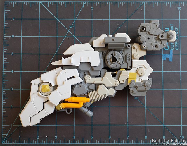
Steps 5.4 and 5.5 build out oddly as new pieces stretch out the rear of the piece. Here's how things look at the end of 5.5...
Regarding 5.5, piece 09-13 is pretty important later on. However, it doesn't sit securly in place. It just sort of loosely floats around. It doesn't go anywhere, but doesn't supply the solid foundation that's required later. This one of many pieces that will need to be glued into place.
In 5.6 and 5.7, I had some obvious flashing in the openings in the 22-18 parts that mask the clear plastic pieces that go in there (37C-8). Those same 37C-8 pieces do not stick hold in place on their own. Be careful or they may be lost to the carpet monster.
Pretty much everything on 5.6 and 5.7 needs to be glued into place. I’m going to run out of masking tape by the time this build is complete.
In 5.8, the two 35-23 parts connect both up top on piece 5.5 (which is oddly mentioned in the guide) and lower on the main part of the piece.
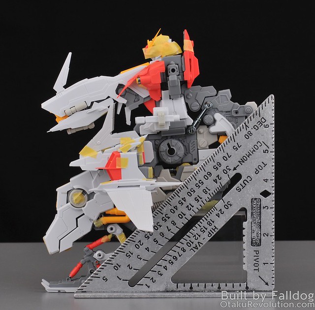
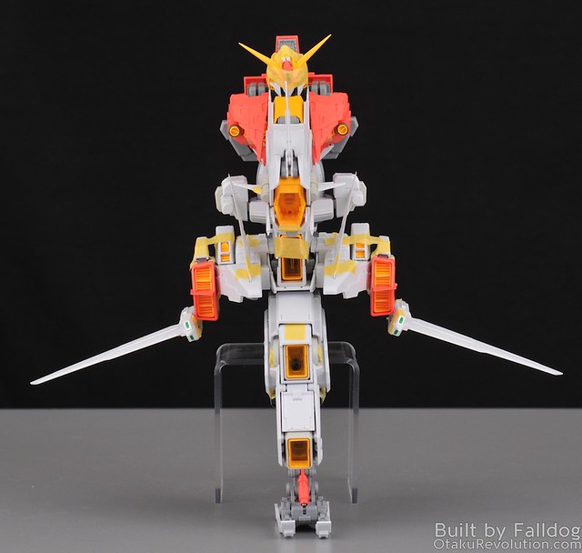
Status Photos
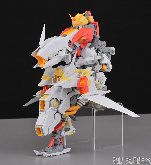
So here's now things look right now. Not really sure what to use as a size comparison at this point so I threw a square with inch markings in there to give you an idea. One shouldn't be too critical at how things don't line up at the front right now. The lack of glue, screws, and that a lot of it is held together in tape means it's a lot looser than a finished build would be. Note that assembly of the completed portions is not supposed to happen until later in the build, it's only like this for the review. I also grabbed the side pieces from step 19.1 thinking they would be important, but they're non-structural and just there to cover the chrome hydraulics.

