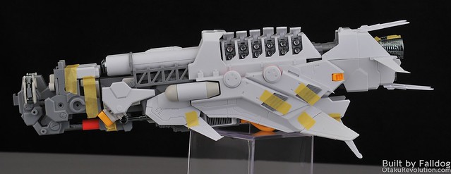
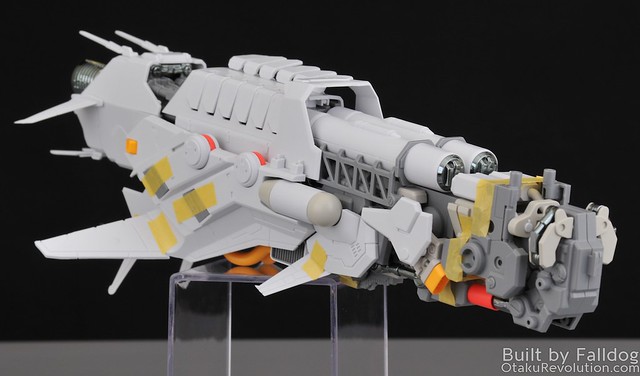
Welcome back to my multi-part review of the of Mechanicore’s 1/100 scale Tief Stürmer. In this section I'm going to review the long booster pod things and the large rear booster.
Review Menu:
- Part 1: Kit Introduction
- Part 2: Head and Torso (Steps 1 through 5)
- Part 3: Booster Pods and Rear Booster Module (Steps 6 and 7)
- Part 4: Main Gun and Radar (Steps 8 and 9)
- Part 5: Arms, I-Field Generator, and Secondary Gun (Steps 10, 11, 12, and 17)
- Part 6: Rear Boosters and Booster Legs (Steps 13 through 16)
- Part 7: Stand and Final Assembly (Step 18 and 19)
- Part 8: Final Kit Review
Common Issues
This is a quick list of the common issues on the build. They apply pretty much across the board and pop up so much that I'd probably go crazy trying to specifically mention each time it occurs throughout the build.
- Beware pegs and holes with fitment issues. Whenever inserting pegs watch to make sure that the peg actually fit. Quite often they're too large for the hole they're supposed to go into. This can be resolved by a properly sized drill bit (use an hand held driver instead of an electric one, or be very careful, to avoid going through the other side of the piece) or with a fine round metal file to widen it from the inside out.
- Beware pieces who's sprue connection often coexists with an important piece. In other words, runners have been connected to the pieces themselves in areas that are also happen to be connection points to other parts of the kit. Never cut flush with the plastic to get it off the runner (which you shouldn't be doing anyway. For the second cut, make sure you check out the part and how it's going used to make sure you don't lop off something important.
- Beware pieces with subtle flashing around the connection points. Connection points may have subtle flashing issues that result in a poor fit. If something doesn't quite work like it should, make sure this is not the case before proceeding. Use of a hobby knife is recommended to clean these areas up.
Build Notes
- There are quite a few piece that really should be glued into place. Since I intend to go back and paint I'm holding things together with masking tape.
- Because I'm going back and repainting I'm not applying any of the metal detail parts at this point. When I finish the build, and add them, I'll add any additional thoughts regarding their application to this review.
Booster Pods (Steps 6.1 - 6.3)
Step 6 features the construction of four booster pod modules (not usre if there's a technical term) which will later be attached to the rear of the kit (two off the rear torso and two off the leg boosters).
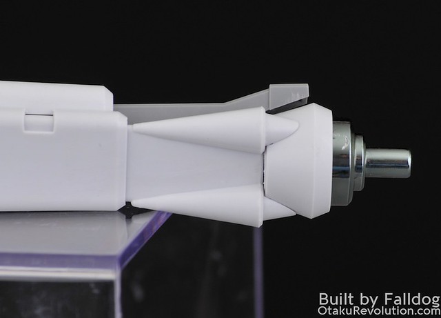
Probably the most ingenious part of this kit (assuming it works properly, I don't have any batteries right now to test) is how the boost LEDs are powered. Okay, a proper system wide circuit would be best, but this is the next best thing. Basically, enclosed in each booster is an LED power unit, a metal cylinder with an LED one end and a screw on connection piece at the other end. When I say screw on connection piece, I mean that the part with the peg is threaded, and screwed into the main cylinder piece. Inside you put the batteries, LED, and the metal cylinder makes up part of the circuit itself. If this works like I suspect, you basically twist the thruster causing the rear metal piece to push the batteries into place, making a connection and powering the LED. The only catch I can think of is that the peg end needs to be glued into place on the kit. Once it's glued into place the twisting mechanism actually shifts the thruster in/out subtly. Without having batteries on hand I can't tell whether this motion is dramatic enough to effect the appearance of said booster placement.
In the first parts of step 6.1, you take 10-19 and and 10-25 and sandwich them together. In the front you need to add 10-26, and the rear 10-5. Here’s the rub, 10-26 has a nice slot to keep the piece in place, 10-5 does not. What I found works best is to take 34-1 and attach it to 10-5 up front. With them seated together properly it’s easier to keep the piece in place. Warning, those two pieces are very tight together, if you overly seat them it’ll be a bitch to separate. On the same note, I’m not sure I’ll ever get 35-6 and 10-7 separated ever again, even after I made adjustments to the connection to account for the chrome paint coating.
Parts 25-10 which connects to 10-19 and 10-25 at an angle which may not be evident in the manual. See the below photos for reference…
That’s only part of it. The key bit is rather hard to explain. See how 25-10’s connecting piece has an angle ot it? Well when you connect 25-10 to 10-19/25 the long end needs to be on the inside, and the shorter end pointing out a bit. The idea is that when you add pieces 10-24 & 10-14, they sort of all sit into place properly. However after that latter part they may be askew a bit. The easy fix to this is to take a tool, like some pliers, and pop it into place afterward. The photos below show a before and after with how they should sit in the piece.
Before...
After...
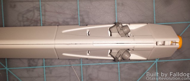
The boost pods have the first installment of some awful seam lines that pop up all over this kit. They aren't that noticeable along the main part of the structure, but are pretty evident at the end...
There's also a weird gap on one of the pieces up front...
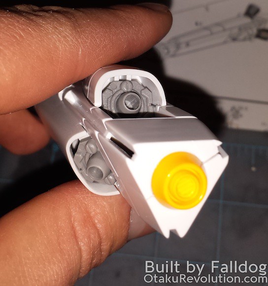
The one thing that bugs me the most is how these pieces don't feature three symetrical sides. Two are alike, and the third is different. Why not make them all the same?
Core Thruster (Steps 7.1 through 7.28)
Again, not really sure what to call this piece. It's the big ass thurster pod thing that sticks out the rear of the torso. It's a lot like http://otakurevolution.com/content/completed-model-kotobukiyas-white-gl…otakurevolution.com/content/completed-model-kotobukiyas-white-glint-from-armored-core-for-answer(just not as cool looking IMHO).
(talkk about looseness of 7.9 and relate back to 06-2)
In step 7.1 you apply pieces 22-24 to the top of 11-1/15. They aren’t sized properly and spread out quite a bit. Photos below should explain it fairly well…
Combination of 11-1/15 and 22-24 from the front
Step 7.5 features a crucial screw component with piece 06-2. This piece screws into one half of the connection pieces and is not supported from the other end. As this piece bears the entire weight of a thruster (step 7.9) unit, and looseness or wiggle will be transfered to the thruster unit. This piece should be glued, and screwed, into place.
In case it’s not clear, after 7.8, one of those pieces goes to 7.9 and the remaining two to 7.7. Gotta love how they don’t have step numbers in order here.
In 7.16 they reference 36-44. There are no pieces labeled 36-44. The one you want is right next to 36-15 and looks similar (just a bit
shorter).
In step 7.19, when you build two 7.21, there are two important things you need to do. The first, is note where the pegs sit on piece 11-5. They, just slightly, sit toward one end or the other. The edge against which the pegs are closest is the leading edge, the one that should have the round cover (32-5). Not having this orientation will create an issue later in step 7.26. For now, when you complete the 7.21 pieces, you should not put them on the kit. Not yet at least.
When you get to 7.26, don’t apply 7.27/7.30 and 7.25/7.28 right away. I recommend putting 7.29 on first. You should also make sure that the connection points to 07-2 (on 7.25/7.28) are super clean first. I don’t think they’re supposed to snap behind 7.25/7.28, but should slide into place. On my runners this connection was way too tight and ill formed.
Once 7.25/7.28 are on, you can add the 7.21 pieces. The latter are far easier to apply without having to work around the tight clearances around 7.21.
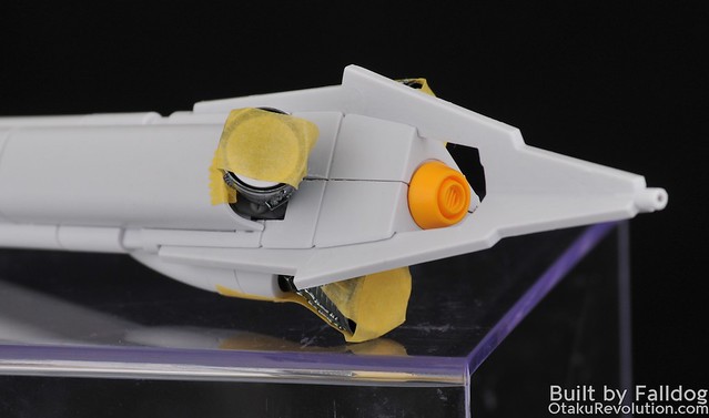
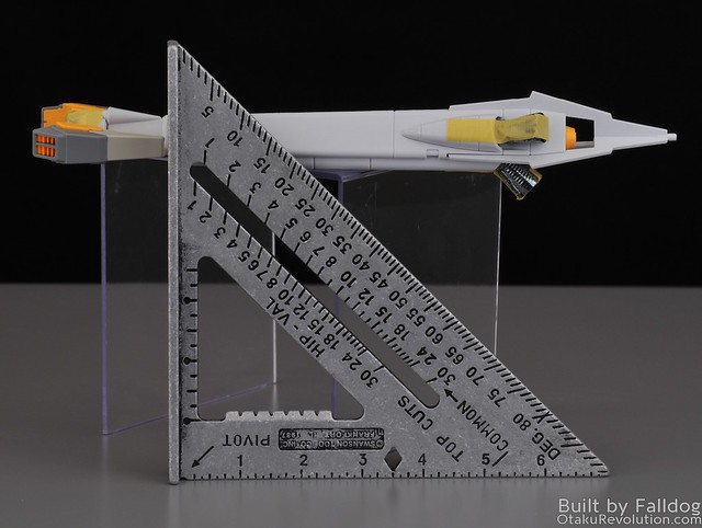
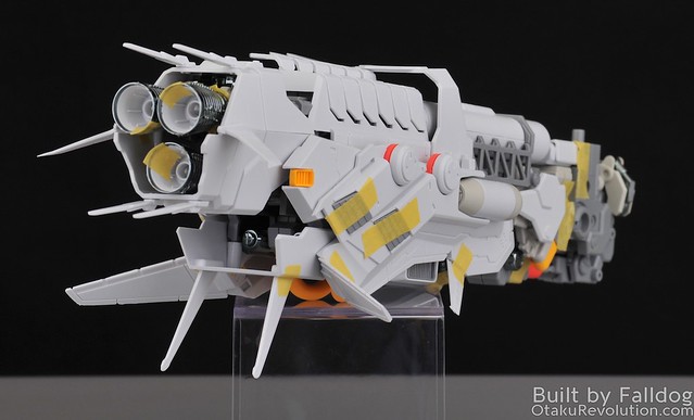
The whole fit of this rear booster section is pretty crappy. Nothing ground breakingly shit, like the head, but very wonky and generally poorly designed. I sort of get the impression that there was an original design that was later built upon to add counter balance weight to the rear of the kit (it's a pretty heavy piece).
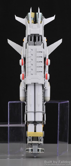
If you look at from the top you can see how some pieces bowe out, either because of how they're situated or how they overlap on top of other pieces. The latter of which, parts 7.25/28, really leave unsightly gaps up above.

